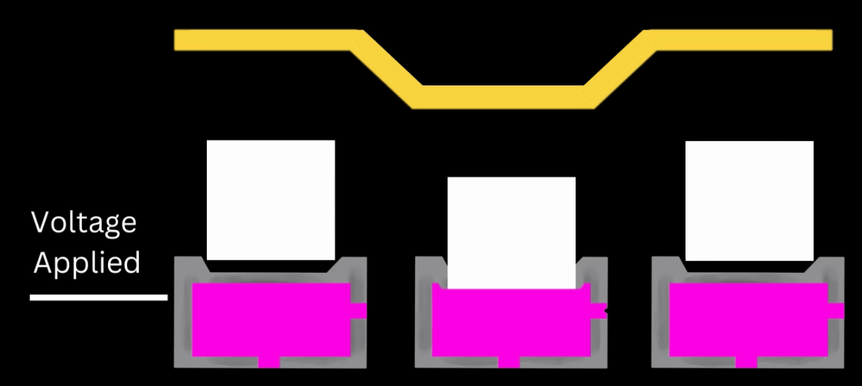
In industrial inkjet printing, the waveform graphically represents and controls the electrical signal sent to the inkjet nozzles inside the printhead, which causes the nozzle to fill and fire. The flexible nozzle chambers respond to the electrical signal, drawing in ink as the nozzle expands and then ejecting a drop as the nozzle contracts. The process repeats thousands of times per second.
Depending on the printhead design, nozzles receive a constant electrical signal and actuate during a drop in the signal. Other systems remain idle until an electrical signal is sent, and then the cycle completes when the signal drops.
Some printhead designs allow the nozzle chambers to move in the positive and negative direction. Some technology uses a combination of both pulses. Regardless of the type of electrical signal, the result produces nozzle jetting.
How Waveforms Affect Printing Performance
As with most projects, the goal defines the steps to the outcome. For printing, the goals most often center on speed and quality. Printing adjustments, including waveforms, revolves around controlling drop size, velocity, and jetting frequency.
Manufacturers calibrate their printheads to hit the sweet spot of performance for the printer’s most common types of ink. Automotive manufacturers do the same with their ignition systems. Mechanics can adjust the fuel and oxygen mixture and the timing to achieve better performances. Both cars and printers can be optimized for better performance based on specific criteria and adjustments.
In the case of printing, a “non-standard” ink may require adjusting the waveforms for optimal jetting.
For example, waveforms may need adjusting if an ink’s viscosity is higher or lower than the ink commonly used in a particular printer.
Waveforms manage the relationship between the wettability of the nozzle’s inner wall and the ink’s surface tension to tune the jetting for optimal performance. The electrical signal increases or decreases droplet breakup and velocity depending on the intended results.
Benefits
- Increase droplet speed or velocity
- Change the volume of the droplet
- Reduce satellites
- Faster turnaround
What Happens in the Nozzle
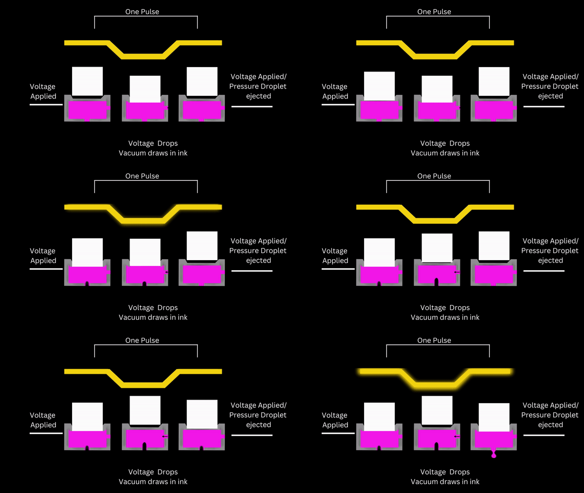 The ink inside the nozzle chamber flows in waves. Because the size of the nozzle and the fluid properties are fixed, the remaining variable is the time to keep the nozzle chamber expanded and allow ink to move back and forth within it at a good rhythm.
A precise pulse width produces the highest drop volume and velocity.
The waves are like engine pistons. If the timing causes the spark plug to be too early or late, the fuel doesn’t create the best compression.
Depending on the waveform used, you can hear a certain rhythm when a printhead is printing. You hear this rhythm from the actuators producing sound waves.
As the ink needs to move back and forth across the length of the chamber, the maximum frequency that a printhead can produce comes down to the size of the printhead chamber and the ink formulation. Sound waves travel through inks differently.
Analyzing and Adjusting Waveforms
Ideally, you’ll need to visualize the jetting as you begin making waveform adjustments. Also, you’ll need a waveform editor to make adjustments sent to the inkjet printer.
Using “drop watcher” equipment creates stop-action images of the inkjet droplets as they are ejected from the nozzle. Most equipment offers real-time analysis and waveform adjustment. The equipment captures droplets with an LED strobe, calibrated camera, and analysis software.
Droplet Analysis
- Determine droplet dimensions
- Calculate volume
- Ligament length
- Satellite number and size
- Speed and velocity
- Identify wetting problems
- Measure trajectory
- Resolution, speed, and frequency
Understanding the Basic Waveform
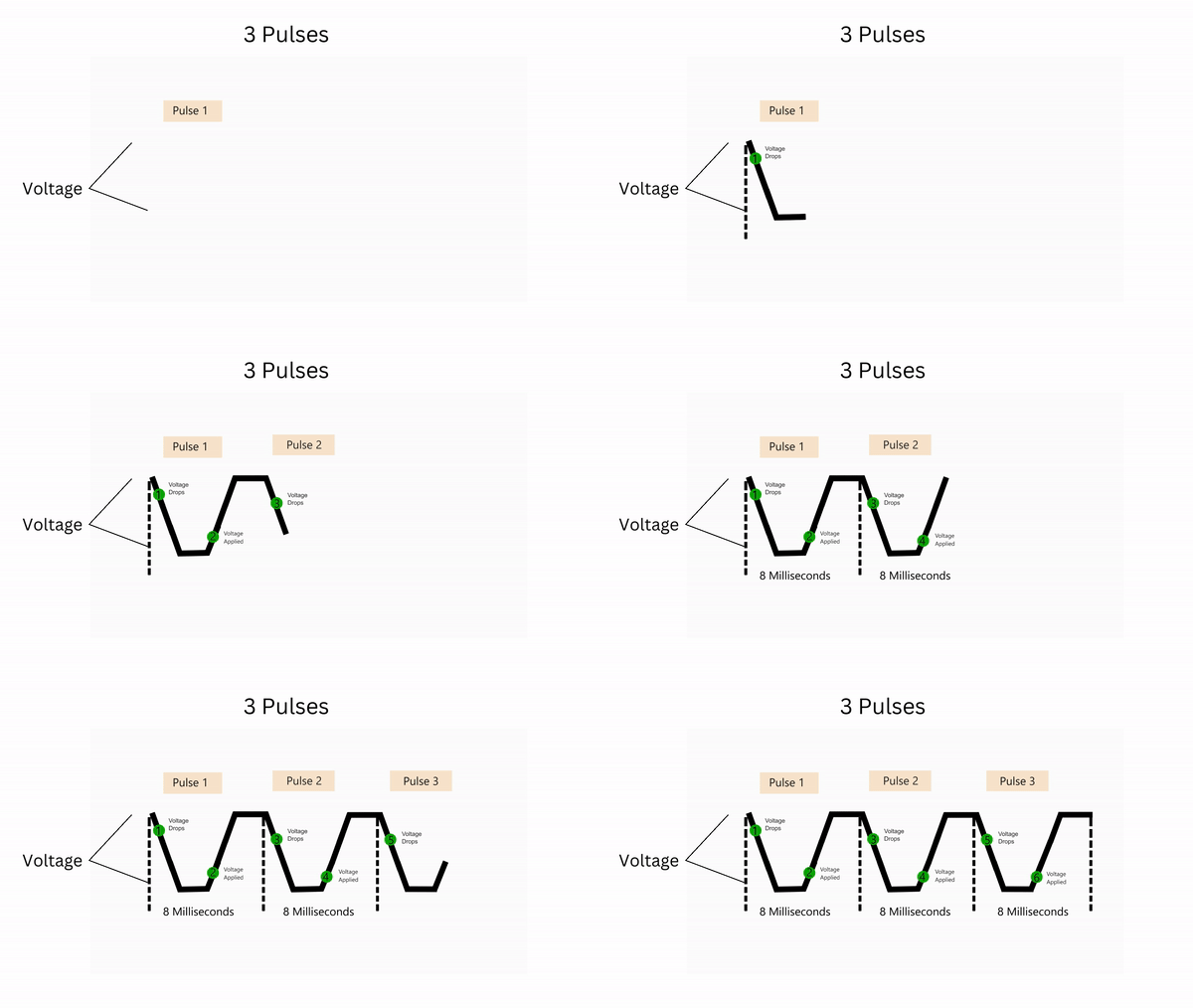 In industrial inkjet printing, the waveform graphically represents and controls the electrical signal sent to the inkjet nozzles inside the printhead, which causes the nozzle to fill and fire. The flexible nozzle chambers respond to the electrical signal, drawing in ink as the nozzle expands and then ejecting a drop as the nozzle contracts. The process repeats thousands of times per second.
Depending on the printhead design, nozzles receive a constant electrical signal and actuate during a drop in the signal. Other systems remain idle until an electrical signal is sent, and the cycle completes when the signal drops.
Some printhead designs allow the nozzle chambers to move positively and negatively. Regardless of the type of electrical signal, the result produces nozzle jetting.
As with any wave, there is amplitude and frequency. In addition, there is a pulse width hold.
The amplitude of the wave characterizes voltage pulse. This initiates the nozzle chamber actuator to pull ink into the chamber. The electrical pulse width holds at the apex for a specified period and then cycles off. At the nadir, another pause begins called pulse spacing.
One waveform may be appropriate for a particular printing application and not for another. Depending on the application, you might need high ink velocity to cover a longer throw distance and be willing to accept satellite droplets.
After modifying waveforms, compare the print quality of each change.
Steps for Optimizing Waveforms
The baseline for your printer is the recommended single pulse for the printhead. Check with your printer provider or manufacturer for the default waveform.
Step 1 – Adjust the Voltage
Proceed with caution when adjusting voltage. To begin, adjust the voltage (amplitude) up and down. Choose precise increments for changes to increase or decrease voltage. Assess the drop speed and satellites.
The greater the voltage, the higher the speed of the droplets will be. The high voltage creates more pressure in the ink chamber. Often the high voltage increases the number of satellites.
Step 2 – Optimize the Pulse Width
Next, the pulse width needs to be optimized – the length of time the signal is activated. The movement of the nozzle chamber matches the direction of the ink during the entire cycle of pulling ink into the chamber and then jetting. When the pulse is synchronized, the wall’s movement and the ink’s direction match. This achieves the maximum velocity of the droplet.
Step 3 – Adjust the Frequency Sweep of Pulse Cycles
After achieving acceptable drop velocity and quality, the next step involves adjusting the frequency sweep of the pulse cycles. For faster printing speeds, a higher frequency is applied – within limits. The higher frequency sacrifices the pauses between cycles. The pulse spacing gives the ink time to stop moving like a wave in the chamber. The pulsing, combined with the continuing ink movement, create unacceptable ink velocity. Frequency sweep is measured in kilohertz (kHz).
After adjusting your waveform, check the printing quality to see if the changes produce the intended results.
Assessing Print Quality
- Raggedness
- Average line width
- Vertical bleed
- Horizontal bleed
- Average radius
- Standard deviation of the radius
- Roundness
Adjusting waveforms requires making a series of choices and sometimes sacrifices. A waveform optimized for quality may sacrifice speed.
Equipment for Analyzing Droplets
ImageXpert Inc. produces high-speed droplet visualization and analysis equipment using a high-magnification camera and strobe light synchronized with the printhead.
Krüss uses two-color light flashes to produce a double-exposure video image, calculating volume, speed, trajectory, and more.
Meteor allows for visualization and analysis for real-time waveform adjustments.
We recommend the optimum voltage for all our inks. Performance depends on the ink, printhead, temperature, humidity, and other factors, and we recommend evaluating waveforms for your application and printing conditions.
Contact experts at Kao Collins for inks, technical support, and specialized ink formulations.


